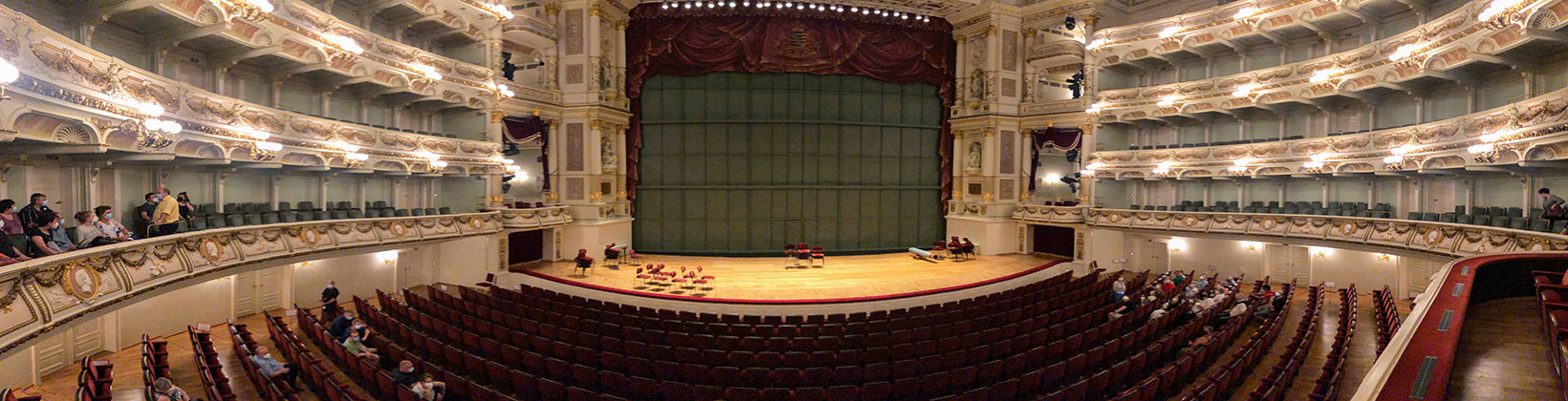
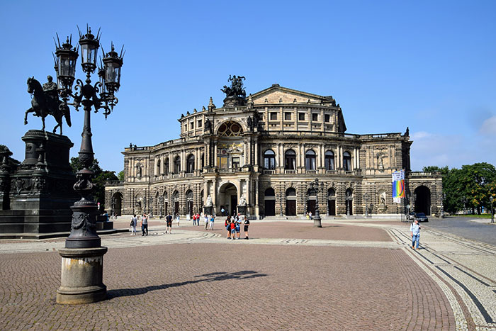
Semperoper in Dresden
The Semper Oper in Dresden is in itself a special architectural sight. World-famous for its special acoustics and incomparable performances, the Semperoper continues to attract large audiences up to the present day. Creo Parametric with add-on applications from B&W has been used to design the stage elements here since 2014.
Stage design in the Semperoper
The previous CAD system was a combination of basic program and add-on software, covering our two requirement areas of mechanical engineering and structural steelwork. With the upgrade to Creo Parametric with Advanced Framework Extension (AFX), the designs became parametric. This proved to be very useful in the design process and especially in deriving the drawings. Even though each stage design holds a new concept and we rebuild our assemblies each time, we can update technically or artistically motivated changes in a drawing more quickly.
Even with the on-board tools, for us mainly the AFX project sub-assemblies, the AFX profiles and the IFX glands, quite a bit can be done. Working with the insertion and movement of profiles on line skeletons in conjunction with the various selectable joints and the profile end trimmings that update as a result is a super thing.
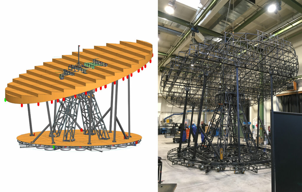
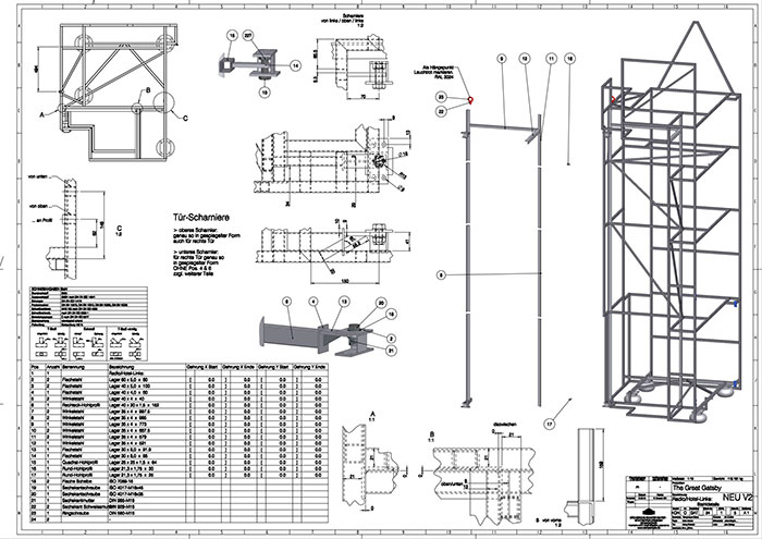
It turned out that due to the lightweight construction of hole section truss structures, comparatively many profiles occur in an assembly and the cutting information for each profile, however, should only take up a small space on the assembly drawing. By means of a cutting table that accesses the parameters of the profiles, the individual profiles including cutting angles can be prepared without the need for a view. This saves many drawings, many dimensions on the assembly view and thus time. You set the view, the table, the BOM balloons and that defines a lot.
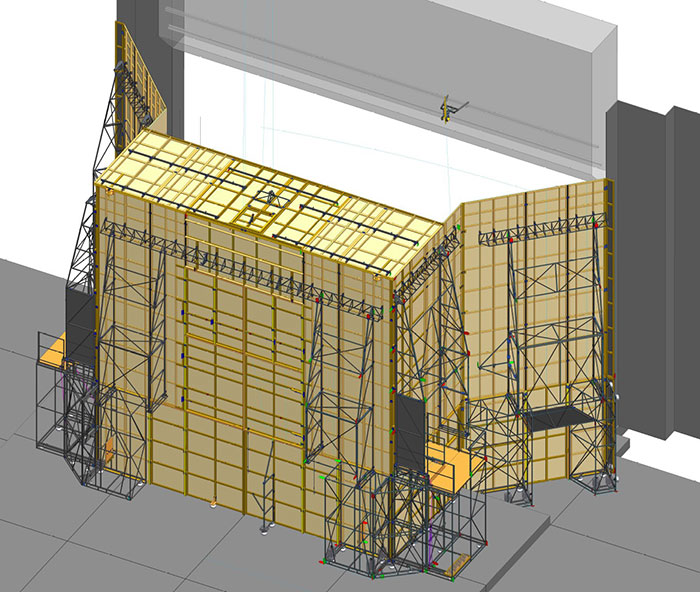
The easy installation of panels has also proven to be very practical for us. We used the accessory element as a copy base for similar wooden panels. This way we can quickly and easily click flooring and wall cladding onto our substructures.
Challenges
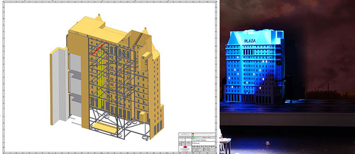
Our assemblies are predominantly artistic in shape and size in the first draft and reflect the goal of the stage designer. Due to the influence of optical details, add-on parts, wooden decking requirements or functional special solutions, it is often necessary for us that a set profile should later be a different size or even a different basic shape, i.e. type. Also, static calculations, which run in parallel with the design process, can lead to other profile requirements. This can cause references to fail in a finished assembly. This then again leads to additional work in the design for new definitions and the new setting of dimensions on the drawing.
Solution
Together with B&W the solution was to develop a universal profile, which is variable in its material, type and size, but remains the same part in its instance. In this way, as an extreme example, we can turn a hollow steel truss into a wooden frame made of theater laths with just a few clicks, of which the drawing is also updated at the same time. More common, however, is the change of a square profile to a rectangular profile or, in the case of a diagonal bracing, the change to a round profile.
Largest joint project
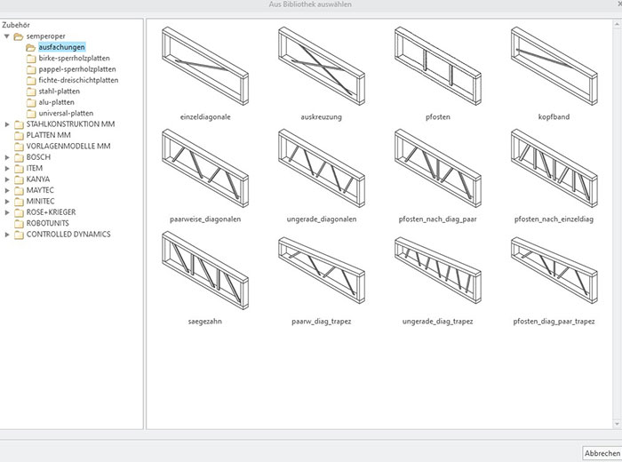
The biggest joint project so far was the creation of a truss generator. The installation of infill based on the previous frame sketch did not lead to a satisfactory result. After all, the installed section widths and the desired gaps in the node area have an impact on the position of the diagonals. The goal was therefore to have a tool that could be used to insert a truss after modeling the form-giving frame; optionally with or without intermediate mullions, in a zigzag or sawtooth shape, or even in a trapezoidal outer frame. B&W developed accessory elements for this purpose, which can be defined by clicking on a few references to obtain the desired truss. Again including all information for the cutting list and also here with the possibility to quickly change the profile type or size afterwards.
Conclusion
The solutions provided by the B&W construction software are an ingenious addition to Creo Parametric and are indispensable to our designs and the associated workflows. Thanks to the user-specific adaptations and extensions, we have a construction kit that provides excellent support for our work in building stage design prototypes. If we ever had any questions or difficulties, we could always rely on the helpfulness, know-how and solution ideas of our B&W colleagues.