How to customize placement rules for blanks in SMARTElectrode
This blog post explains how you can customize the blank placement rules to suit to your needs.
SMARTElectrode offers the possibility of preparing different types of blanks – e.g. round or square. When creating the electrode base, the software selects a blank from the list of available sizes. A data file (.dat) describing available sizes and dimensions belongs to each template type. It’s a tab separated file and can be opened to add or remove sizes. Open template file in <configuration>\electrode\<supplier>\<type>.dat to modify.
The behavior during placement can be changed by adjusting these values and some options.
Description of data file content
| # | Name | Description | Image |
| 1 | Instance | Name of selected size. Appears in Base UI. | |
| 2 | A_BASE | Length (X-dimension) of blank | 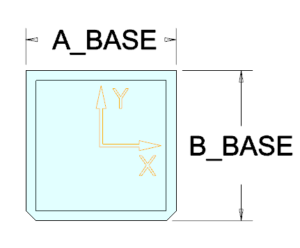 |
| 3 | B_BASE | Width (Y-dimension) of blank | |
| 4 | LENGTH | Blank length | 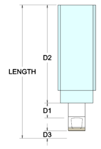 |
| 5 | D1 | Normal distance from workpiece to base | |
| 6 | D2 | Base height | |
| 7 | D3 | Top offset from electrode tip to blank length | |
| 8 | FRAME_WIDTH | Circumferential offset for templates including a measuring frame | 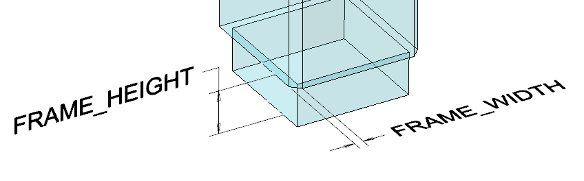 |
| 9 | FRAME_HEIGHT | Frame height for templates including a measuring frame | |
| 10 | CHAMFER1 | Chamfer in –X / -Y direction of blank | 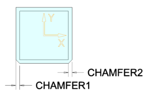 |
| 11 | CHAMFER2 | Chamfer in +X / -Y direction of blank |
Optional data
- Minimum value used for free values
- Name of predefined template for CAM
- Name of holder to be used with this instance
- Predefined offset to be used with holder
Normal behavior – Installation state
Settings
- All values in data file are set
- LENGTH = 50
- D1 = 5
- D2 = 20
- D3 = 0
- Options
- INCREMENT_SIZE = 1.0
Defines the increment blank dimensions are rounded to - INCREMENT_POS = 0.5
Defines the increment Z position of base is rounded to
- INCREMENT_SIZE = 1.0
Processing
- Height of contour will be rounded to a value, where
- D1 corresponds at least to value in data file D1 ≥ 5.0
- Z position of base rounded to INCREMENT_POS Z = 30.0
- Blank length = 50
- Base height = 20
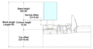
- Top offset D3 = 19.45
As blank length and base height are fix values all the remaining height is added to D3.
Note
Normal offset D1 and top offset D3 are measured values, no dimensions! They define minimum values and are allowed to get bigger!
Result
Example 1: Even contour height
Note
This enhancement is available since SMARTElectrode 12.0.5.0 and 13.0.1.0.
Task
Contour height including D3 should be rounded to even value; The software can freely assign the value for Z position of base.
Settings
- Values in data file are set
- LENGTH = 50
- D1 = 5
- D2 = -1
Allows the software to calculate the value - D3 = 0
- Options
- INCREMENT_SIZE = 1.0
- INCREMENT_POS = 0
To allow exact value without rounding
Processing
- Height of contour will be rounded to a value, where
- D1 corresponds at least to value in data file D1 ≥ 5.0
- Contour height is rounded to INCREMENT_SIZE = 11.0
- Z position of base is set to Z = 30.45
- Blank length LENGTH = 50
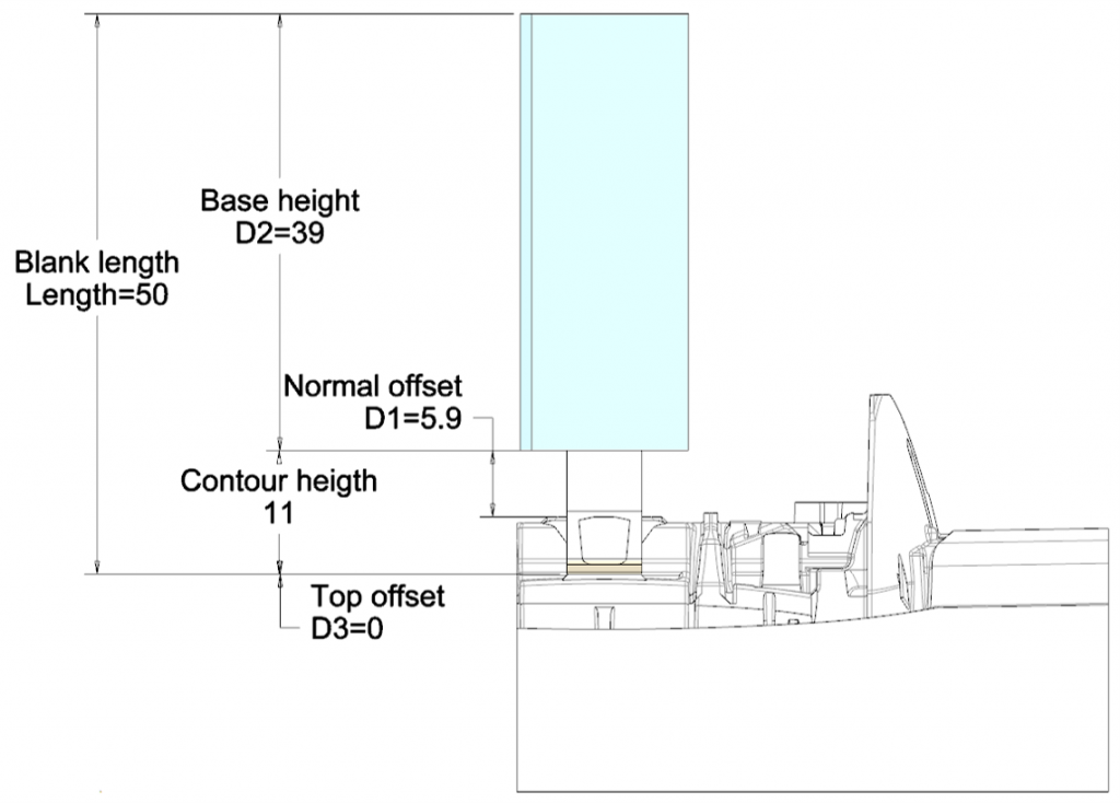
- As a result base height will be set to a value, where…
- Top offset D3 = 0.3
Corresponds exactly to the value in data file - Base height D2 = LENGTH – Contour height – D2 – D3 = 39.0
- Top offset D3 = 0.3
Result
Example 2: Minimum base height
Task
Base height D2 should be set to minimum value; top offset D3 should be given an exact value.
Settings
- Values in data file are set
- LENGTH = 50
- D1 = 5
- D2 = -1
Allows the software to calculate the value - D3 = 0.3
- Options
- INCREMENT_SIZE = 0
To allow exact value without rounding - INCREMENT_POS = 0.5
- INCREMENT_SIZE = 0
Processing
- Height of contour will be rounded to a value, where
- D1 corresponds at least to value in data file D1 ≥ 5.0
- Z position of base rounded to INCREMENT_POS Z = 30.0
- Blank length LENGTH = 50
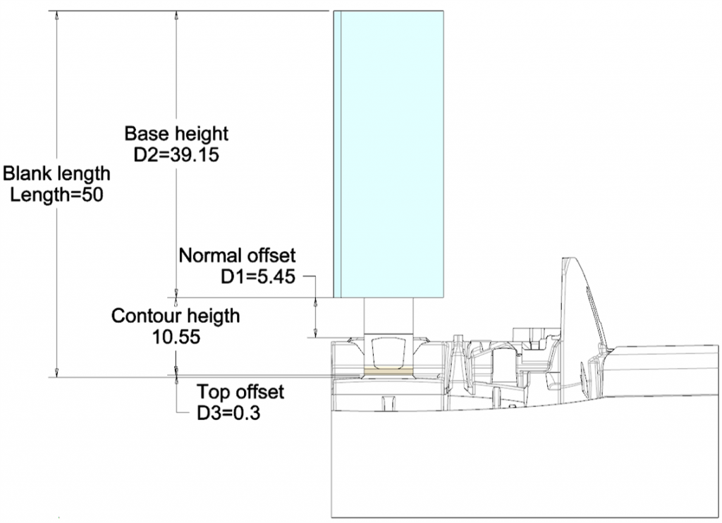
- As a result base height will be set to a value, where
- Top offset D3 = 0.3
Corresponds exactly to the value in data file - Base height D2 = LENGTH – Contour height – D2 – D3 = 39.15
- Top offset D3 = 0.3
Result
Example 3: Minimum blank length
Task
Blank length should be set to minimum value and top offset D3 should be given an exact value.
Settings
- Values in data file are set
- LENGTH = -1
- D1 = 5
- D2 = 20
- D3 = 0.3
- Options
- INCREMENT_SIZE = 0
To allow exact calculation without rounding - INCREMENT_POS = 0.5
Defines the increment Z position of base is rounded to
- INCREMENT_SIZE = 0
Processing
- Height of contour will be rounded to a value, where
- D1 corresponds at least to value in data file D1 ≥ 5.0
- Z position of base rounded to INCREMENT_POS Z = 30.0
- Base height = 20
- Top offset D3 = 0.3
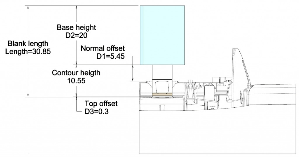
- As a result blank length will be set to a value, where
- D3 corresponds exactly to the value in data file
- LENGTH = Contour height + D2 + D3 = 30.85
Result
We hope that you like the new features and that they will make your work easier. If you have any experience with the new functionality, please feel free to share it with us. We are also happy to receive further ideas for improvement, as we are constantly working on optimizing our software for you. Please feel free to give us feedback.
This could be interesting for you
-
New Creo Version available
-

Review: PTC/USER 2026
-

Fachkonferenz Digitalisierung 2026 in Stuttgart
-

Join us at PTC/USER Global Summit 2026
-
Review: User Meeting – Toolmaking in Creo 2025
-

Future of B&W has begun
-

No security alert of B&W License Server 11.19.1.0 regarding lmadmin
-

Potential issues in running B&W Software products in Creo 9.0 and 10.0
-

Meet us at the PTC/USER Global Summit 2024 in Orlando!
-

User Event Tooling 2023
-

Successful Windchill implementation project
-
SMARTElectrode 19.4 for Creo Parametric 13 now available
-
New SMARTElectrode Versions released
-
Technology Parameters for Interface to Zimmer & Kreim Alphamoduli
-
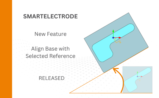
Align Base with Selected Surface
-
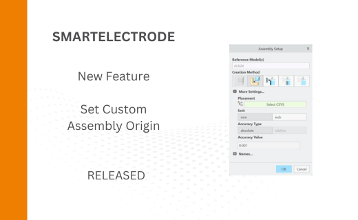
New Electrode Assembly with Custom Origin
-
New Version for IFX out now!
-
Additional Washer and Nut for IFX
-
New Logging Options
-
Improved translation of library files in IFX
-
PTC/USER Agenda